TD AXIOM / Product development preview

Design bolted joints
with traceable evidence.

VDI 2230 · Visual engineering · AI assistance

Start with a drawing or CAD model and work through preload, strength verification and calculation reporting. Review and revise the engineering decisions in one workbench.

Standalone desktop software · VDI 2230 design verification · Optional AI assistance

Thread Designer® Engineering Suite 4.0 · Development preview

AN ENGINEERED CONNECTIONB1 / CAD EXAMPLE
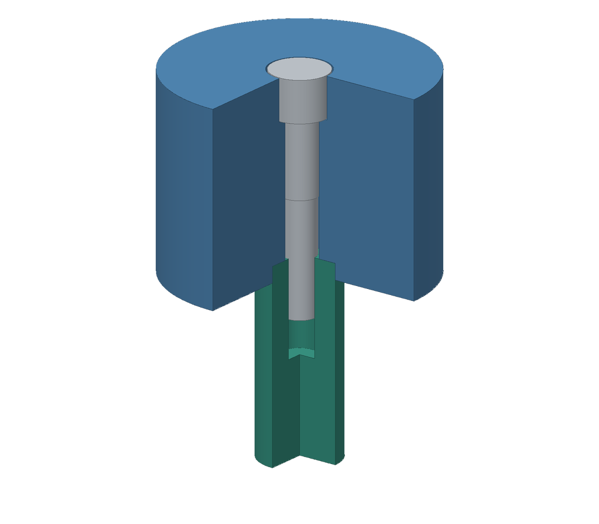
B1 CAD model · clamped members are cut, screw is fully displayedDrag rotation · Highlight selected parts
FROM GEOMETRY TO ENGINEERING DECISIONSGeometry, operating condition, verification, and calculation book, form a continuous design process.↓

01 / THREE WAYS IN. ONE ENGINEERING PROJECT.

Where does your design start?
Axiom works with the inputs you have.

Model from known dimensions, define calculation objects from existing CAD, or use AI to help interpret a drawing and build a model. Each route leads to the same inputs, checks and deliverables.

01

Start with parameters

Select the fastener and joint configuration. Define dimensions, materials, assembly method and operating conditions. Parameters stay linked to the geometry so changes remain traceable.

Standard fastener · Multi-layer clamped parts · Parameter-driven.
02

Start with existing CAD

Retain the part geometry and identify bolt axes, bearing faces and contact interfaces. Use that information to build the engineering model directly from CAD.

Parts and assembly · Face selection · Geometric simplification and verification.
03

Start with drawings and requirements

Provide drawings, materials and design objectives. AI helps extract dimensions and organize modeling and verification steps. Engineers control critical decisions and approved changes.

Drawing understanding · Tool execution · Result verification

02 / THE REAL AXIOM WORKSPACE

Review the structure and its data
in the same workbench.

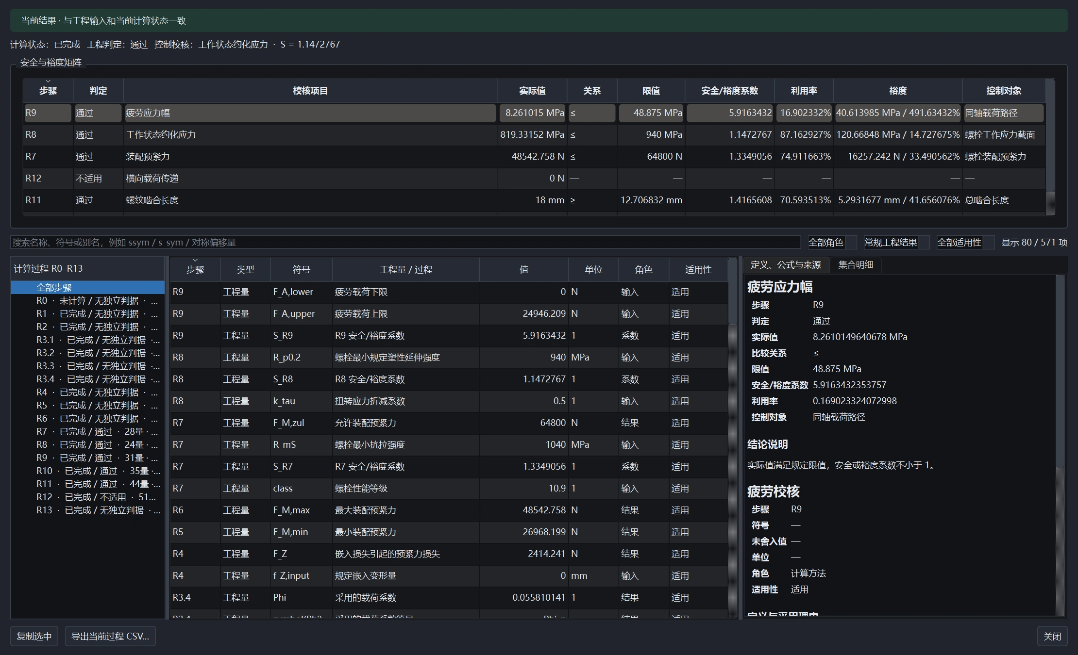
The B1 example shows the model, materials, loads, verification results and calculation report. Trace each result to the workbench objects and parameters.

TD AXIOM / ACTUAL DESKTOP CAPTURE
The 3D structure sits alongside the project tree. Parts, materials, assemblies, and contact relationships are organized in the same project.Real Software Screenshot · Development Version · Example Project

Clear object referencesParameters refer to specific parts, bearing faces and contact interfaces, so each value has a clear physical reference.

process continuityAfter modifying the input, check the related geometry and results, so that subsequent judgments are based on the current engineering context

result availableReview the calculation steps, parameters used, and applicable conditions from the safety factor perspective.

03 / FROM DRAWING TO A WORKING PROJECT

From a drawing
to a joint design others can verify.

Read the diagram, construct the solid, configure the engineering, execute the verification, and organize the calculation book. AI understands the design intent and proceeds through software internal objects and operations. Each stage has verifiable inputs, geometry, and results.

Drawing → 3D → VerificationB1 example process · Click stage can be viewed step by step
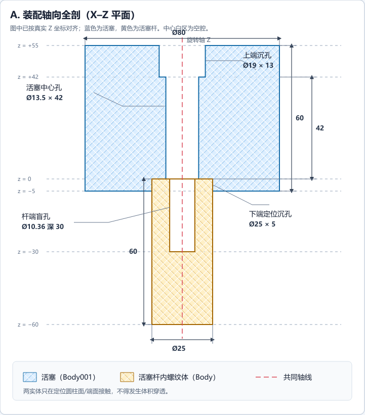
INPUT / B1 Modeling Reference Diagram
B1 Piston and internal thread profile, annotated with outer diameter 80, center hole 13.5, and blind hole 10.36 deep 30, units in mm.
Dimensions / mmØ80 · Ø13.5 · Ø10.36 × 30
OUTPUT / ENGINEERING GEOMETRYwaiting to start
Geometric target preview

Use dimensions
to define the joint.

The piston is coaxially aligned with the internal threaded body, and the screw is supported on the stepped hole.

Source B1 CAD target structure preview
From readable dimensions, build verifiable geometry.
piston outer diameterØ80 mm
bolt through holeØ13.5 mm
Effective clamping length42 mm

Dimensions are taken from B1 engineering reference drawing, can be magnified for individual verification.

01 / Understand the drawing

Identify profiles, holes and assembly relationships first.

Read the outer diameter, stepped hole, blind hole depth, and coaxial relationship. Geometric dimensions and thread engineering definitions are recorded separately. Missing or conflicting information is left to the engineer to judge.

B1 case flow demonstration: Reference figure, CAD model, and results come from the same engineering. The web page plays the pre-set steps without calling AI, and the playback duration does not represent actual processing time.

Open B1 software results excerpt ↗
UNDERSTAND

Interpret the design objects

Know what 'this material', 'this hole', and 'this modification' refer to. Drawing information, existing engineering, and user requirements enter the task context together.

ACT

Make and review changes

Complete modeling, input, check, and calculation through software tools. It can handle tasks from scratch and also continue modifications on existing engineering.

REVIEW

Collaborate with supporting evidence

Show plans, changes, engineering assumptions, and execution results. Tasks can be paused, and key decisions are confirmed by engineers.

MORE THAN ONE WORKFLOW

“Review my current design”

Read current engineering, locate control items such as clamping force, fatigue, support surface, or thread engagement, and explain why.

“Compare two design changes”

Change specified parameters while retaining the baseline scheme, compare the benefits, costs, and new constraints.

“Turn the results into a calculation report”

Connect formal input, calculation results and basis, form a structurally complete report, then reviewed by engineers.

04 / VDI 2230, AS AN ENGINEERING WORKFLOW

Thirteen steps for
a completejoint verification.

From assembly scatter and required clamping force, to compliance, load distribution, and preload, to static strength, fatigue, bearing, engagement, and tightening torque. Each conclusion is not an isolated single number.

Select step, view the problem it solves

R3Design and Verification Chain

How does the joint distribute the working load?

INPUT / basis

OUTPUT / Results

What does this mean for the design?

clear requirements→solution preload→check limit→determine assembly

R0 is used for preliminary specification and geometric dimension estimation; R1–R13 constitute the main line of subsequent calculations. The specific standard version and applicable conditions will be specified in the engineering context.

assemblyCombined action of tension and torsion
static strengthLimit under service load
fatigueAlternating stress and life risk
bearing pressurelocal pressure on the bearing surface
engagementLoad-bearing capacity of internal and external threads
transverse force transmissionSlip resistance and shear

05 / ONE CHANGE. A VISIBLE CONSEQUENCE.

Change a parameter
and see what it meansfor the joint.

First clarify the conditions that remain unchanged, then change one quantity, and finally compare the results. The following two interactions are independent: one explains assembly, the other explains service.

01 / Friction during assembly

Why does bolt force change at the same 80 N·m torque?

Fix the thread, support size, and total torque, and only change one friction. The current point on the curve is the preload obtained under these conditions.

fixed conditions M12 × 1.75 · 80 N·m

Thread pitch diameter d2 = 10.863 mm
Effective support friction diameter DKm = 16.0 mm

Support Friction μK = 0.120 (Fixed)

0.120
0.0600.240
Preload Force FM 40.0 kN

Reference state: μG = μK = 0.120

Coefficient of friction → Preload force

Total torque is always 80 N·m

When friction increases, the torque required to achieve the same axial force increases; the total torque remains 80 N·m, so the actual obtained preload decreases.

Where is this 80 N·m applied?

Sum of three terms is constant
pitch term
——
thread friction
——
supporting friction
——
View calculation conditions and equations

Use the standard metric 60° thread for torque balance. DKm Yes, this is the effective friction diameter given in this experiment; the thread pitch uses the basic size of M12 × 1.75. The two frictions are input separately. After switching experiments, the friction coefficient not selected is fixed at 0.120.

FM = MA / (aG + aK)

aG = (d2/2) · (tan λ + μG/cos 30°) / (1 − tan λ · μG/cos 30°),tan λ = P/(πd2);aK = μKDKm/2。

current aG = — mm,aK = — mm。MA When calculated in N·m with the lever arm in mm, the result is F.M unit is kN.

pitch term MP = FMP/(2π); thread friction term = FMaG − MPSupport friction term = FMaKTorque is allocated based on actual calculation results; individual values are retained to two decimal places, and the total is calculated using the non-rounded value.

This experiment shows the torque-preload relationship under determined friction conditions. Formal assembly design also needs to consider the friction range, tool scatter, strength, and support pressure; 80 N·m is a demonstration input.

Reference formula:NASA《Fastener Design Manual》,Fastener TorqueParameter distinction reference Bossard torque and preload calculator。

02 / Load Distribution of Preloaded Connection

Why does the bolt take only part of the increase in external load?

This time, the fixed preload and stiffness on both sides are kept, and only axial tension is increased. Using the classic force-deformation diagram, observe how bolt loading and clamped member unloading occur simultaneously.

fixed conditions preloading force FM = 40 kN

Bolt stiffness cS = 200 kN/mm
clamping stiffness cP = 800 kN/mm
Axial tension · Load introduction on support surface · n = 1

Load distribution coefficient Φ = 0.20

25.0 kN
0 kN50 kN · Separation boundary
bolt force FS45.0 kN

relative assembly +5.0 kN

remaining clamping force FK20.0 kN

relative assembly −20.0 kN

Service additional deformation u0.025 mm
Contact keep closed

Classic preload joint force-deformation diagram

Assembly Point M → Current Service Status
bolt elongationCompression and unloading of the clampaxial external load FA
At the same deformation position, the difference in force between two points is the external loadFS − FK = FA45.0 − 20.0 = 25.0 kN

After applying 25.0 kN axial tensile force, the bolt increases by 5.0 kN tensile force, and the original clamping force decreases by 20.0 kN; together they satisfy the external load balance.

The rising line is measured from the left origin for bolt elongation; the falling line is measured from the right zero force point in reverse for clamp compression. During assembly, bolt elongation fSM = 0.200 mm, clamp compression fPM = 0.050 mm. After service, two points move to the right along the same additional deformation u.

Examine the relationship between force and deformation, as well as separation boundaries.

Use a coaxial, linear elastic, n = 1 dual spring model, with load introduced from the support surface. This experiment fixes the assembly preload at 40 kN, independent of the upper friction test; no account is made of embedded losses, temperature changes, or bending.

Φ = cS / (cS + cP) = 0.20

FS = FM + ΦFA;FK = FM − (1 − Φ)FAUnder this stiffness, each increase of 1 kN external load increases the bolt tension by 0.2 kN and decreases the clamping force by 0.8 kN.

u = FA/(cS + cP) u is the additional elongation of the bolt, which is also the compression rebound of the clamped part. When contact closure occurs, it is not the interface gap.

FA,sep = FM/(1 − Φ) = 50 kN. When reaching this boundary, FK = 0,FS = FAThe slider stops here; the separation state after continued loading is not included in this experiment.

This figure explains the basic elastic relationship. The actual load introduction, eccentricity, local separation, and complete strength determination of real connections should be calculated using actual structures and operating conditions.

Illustration and basic relationship reference:NASA 'Fastener Design Manual', Figure 27;GWJ eAssistant,VDI 2230 Joint Diagram。
06 / DESIGN IS A BALANCE

Good design starts with
understanding the limitingsafety check.

Low preload may cause the connection to lose function; high preload may cause assembly and local loading to become limiting factors. Axiom hopes to move the scheme selection from repeated trial numbers to targeted comparisons.

WHAT ARE YOU TRYING TO IMPROVE?

Identify the limiting check before choosing a design change.

Select a design problem, and view the benefits and constraints that need to be considered simultaneously.

adjustments that can be studied

Need to be verified together

Retain the baseline scheme, compare input changes, control verification, and assembly parameters under the same operating condition.Do not replace complete judgment with a single indicator.

07 / FROM AN ANSWER TO A DELIVERABLE

A calculation should produce
evidence that otherscan review.

Organize parameters, formulas, stage results, control conditions, and assumptions into a calculation book. Designers can continue modifying, reviewers can check the logic, and assembly loops can find the required parameters.

Screenshot of the calculation report · B1 example draft
01

Show conclusions alongside the limiting checks

Presentation uses input, calculation steps, margin, and control items. Readers can understand the results and know under what conditions the conclusions are valid.

02

Keep assumptions and sources in the report

Clarify user input, standard data, geometric measurement, and engineering assumptions to avoid losing references during discussion and modification.

03

From research to design handoff

Face scheme argumentation, design verification, and assembly parameter communication. This example is a draft of the calculation book, and formal delivery requires completing engineering drawings and review.

Open B1 software results excerpt ↗
Drawing / CAD / Input→geometry and engineering objects→VDI calculation chain→verification and assembly parameters→design manual

For the same engineering project, retain the path from problem to conclusion.

08 / ONE FOUNDATION, MANY CONNECTIONS

Go from a single bolt
to a practicaljoint design.

Product planning focuses on connection objects, loading modes, and working stages, rather than just a single standard example. Applicability and necessary engineering simplifications must always be clearly defined.

Joint geometry

Through-hole bolt—nut connection, inset connection, multi-piece clamping components, ring and prism parts, and connection structures with eccentricity.

Loads and operating conditions

Axial and lateral loads, moments, working load range, assembly scatter difference, embedded loss and temperature effects.

From design to review

Pre-specification selection, existing structure verification, scheme adjustment, parameter sensitivity comparison, and communication with reports and assembly parameters.

Working with joint groups

Around clear load distribution and representative bolts, develop verification engineering. Retain the conditions and results of each member, and do not treat the entire group of loads as the load of a single bolt.

09 / BEFORE YOU START

Questions
about Axiom

Understand Product Progress, AI Collaboration Methods, and the Applicability of Web Cases.

What stage is the software currently in?+

Axiom is currently in the development stage. The page includes current software screenshots and planned function demonstrations; the function range, system requirements, and delivery method will be explained at the official release.

Will AI Replace the Engineer's Judgment?+

No. AI is used for understanding tasks, organizing steps, and executing software operations. The calculations still come from engineering models and tool results. Key operating conditions, design criteria, important assumptions, and final engineering conclusions require engineer verification.

Can design and verification be conducted without AI?+

Axiom is based on independent engineering software. Parameter input, CAD organization, VDI calculation, result verification, and calculation book are not solely entered through chat; AI is a collaborative method, not a replacement for the engineering core.

Are the charts on the web page the complete VDI 2230 calculation?+

No. The two interactions separately show simplified assembly torque relationship and axial force-deformation relationship. Fixed conditions and boundaries are listed in each diagram. They are for understanding the mechanism, not for direct use in issuing design safety conclusions.

Will drawings and engineering data be automatically uploaded?+

This web page does not upload files or call AI services. Formal software AI collaboration requires explicitly defined sending ranges based on selected services and permissions; check local data management and external model request permissions before use.

Carry design evidence into verification and use.

TD Axiom establishes design benchmarks for joints using standard methods. When further research is needed, find the corresponding professional tools along the current issue.

Clarify Input Basis
TD Atlas Organize standard, material, and method knowledge to help verify the sources, versions, and applicable conditions of Axiom design inputs.
Deep into local and global
Detailed issues with thread profile, thread root, and zone of engagement are handled by TD Forge Expand; the overall response of complex structures, contact, and connection groups is by TD Nexus Expand. Before comparing results, load, material, and boundary conditions must be unified.
Connection testing, assembly, and in-service
TD Sense Organize experimental measurement and analysisTD Cadence Faced with assembly process and qualityTD Sentinel Focusing on in-service observation and maintenance records. Collaboration planning focuses on the correspondence between design objectives, process records, and subsequent verification.

Cross-product data collaboration belongs to the kit planning direction, specific integration is subject to official release notes.

DESIGN WITH A REASON. BUILD WITH CONFIDENCE.

Build your next joint design
with a complete engineering workflow.

Learn about TD Axiom's development progress, exchange your structure, operating condition and design requirements

haoyuruilianTJ@163.com

real software interface

Real software screenshot · Example engineering

Demonstration and engineering basis

The screenshots and 3D model are from the B1 example project. The screws use equivalent thread geometry. Section and exploded views show the part structure. Colors distinguish components.

The drawing modeling process is played back according to preset steps without calling AI. Two groups of interaction mechanisms are calculated in the browser to understand simplified relationships; full design verification requires actual engineering inputs.

The VDI workflow follows the calculation steps and force–deformation relationships of VDI 2230 Blatt 1:2015. The diagrams were redrawn for explanation. VDI certification or software authorization is outside the scope of these illustrations.

The web does not upload engineering files or enable third-party statistics. Provide calculation conditions, equations, and reference materials beside the charts.